
Jungheinrich Diagnostic Fault Codes
Warehouse equipment malfunctions and their diagnostics

Progress does not stand still, adding all new units to the device of technology, therefore, the design of special machines only becomes more complicated every year. However, the more complex the technique, the more difficult it is to maintain and diagnose.
Fortunately, to facilitate the work and quickly analyze breakdowns and emergency situations, special sensors were invented that provide servicemen with information about specific breakdown points. Such a system has been operating in the automotive industry for a long time and has proven itself to be the best.
The requirement for loading equipment is no exception, since its downtime can cost a business a lump sum. It is important that timely and fast diagnostics and troubleshooting become top priorities.
To make it easier for the maintenance service of warehouse equipment (reach truck, forklift and electric stacker) to work, special error and error codes have been invented, which indicate the exact problems that have arisen with the equipment. Such a system not only speeds up the repair work, but also eliminates the human factor.
What codes are there
Codes are divided into errors and malfunctions. All of them can be easily diagnosed and corrected in a short time.
The most common problems and errors that can be diagnosed using codes
- Wrong learning operation warning
- Short circuit top and bottom FET
- Upper side short circuit
- Bottom side short
- Phase U wire damage
- Phase V wire damage
- Phase W wire damage
- Temperature increase
- Temperature is abnormal
- Short circuit of load circuits
- Pump motor (Temperature rise)
- Pump motor (Temperature abnormal)
- External controller input signal is out of regulatory range
- Faulty temperature sensor of the controller of loading and unloading operations
- Malfunction of the temperature sensor of the pump motor
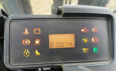
Also, special icons on the instrument panel can signal the need for maintenance, replacement of technical fluids, or the change and selection of a new battery. The main thing to remember is that, despite the seeming simplicity of warehouse equipment, in no case should you try to correct mistakes yourself. To avoid costly costs, it is always best to contact a qualified after-sales service. She will promptly and efficiently fix all the problems, and you will not have to worry about anything. Moreover, in the case of self-repair, you may lose the warranty on your equipment. Since only after service repairs, the percentage of repeated breakdowns will be minimized.
An electronic diagnostic system enables technicians to efficiently troubleshoot faults. Optimum equipment of the service vehicle and all the necessary spare parts for the fastest possible troubleshooting and minimizes downtime.

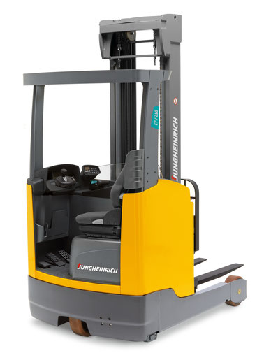
This diagnostic device allows proactive diagnostics and parameterization of the widest range of Jungheinrich specialist equipment.
Jungheinrich forklifts are diagnosed with an adapter.
DFG-320
ETV-12
EJE-220r
ESD-120
EFG-215
EFG-320
ETV-216
ETV-325
EFG-425
ETV-214
EJC-12
ECE-118
EFG-216k
AM-22
DFG-20
EKS-210
ETV-114
EJE-120
EFG-216
DFG-316
ESD-220
ETV-112
EFG-113
EJC-112
Jungheinrich Diagnostic Dispaly Fault Codes List. Free Download PDF Fault Codes
Jungheinrich Fault Codes Download
Jungheinrich EJC112 & E1202 Event Messages Codes List Download
Jungheinrich Error Codes List Download
Jungheinrich Fault Codes Download
Jungheinrich LISTADO ERRORES Download
Jungheinrich System Error Codes list Download
Jungheinrich System Error Codes list Download
Jungheinrich System Error Codes list Download
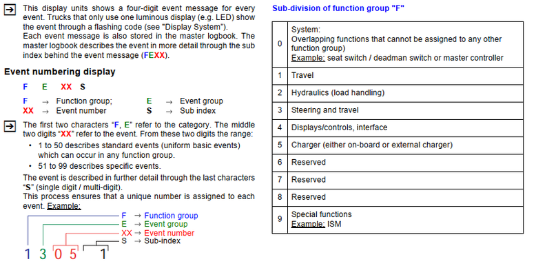
|
F |
E |
XX |
S |
Operational |
Description |
Cause / Triggering Event |
Action |
|
_ |
1 |
01 |
1 |
System start |
Supply via unexpected key |
Evaluation of three key switch inputs. Possible |
- Check key switch input connection against the |
|
_ |
1 |
02 |
1 |
Self test |
Contact closed instead of |
On power-up the capacitor voltage should be one volt |
- Test the main contactor output of the controller; |
|
_ |
1 |
2 |
Self test |
Contact open instead of |
When the main contactor has switched on the capacitor |
- Test the main contactor output of the controller; |
|
|
_ |
1 |
3 |
Self test |
Main contactor permanently |
An attempt is being made to open the main contactor. |
- Replace controller; |
|
|
_ |
1 |
4 |
Self test |
Main contactor feedback |
Feedback signal from main contactor status implausible |
- Test the main contactor output of the controller; |
|
|
_ |
1 |
03 |
1 |
Self test |
Output transformer faulty |
The semi-jumpers 1, 2 and 3 are controlled in turned for |
- Replace controller; |
|
2 |
Self test |
Output transformer faulty |
|||||
|
3 |
Self test |
Output transformer faulty |
|
_ |
1 |
04 |
1 |
Self test |
Output transformer faulty |
Semi-jumpers 1, 2 and 3 are controlled in turn for |
- Replace controller; |
|
2 |
Self test |
Output transformer faulty |
|||||
|
3 |
Self test |
Output transformer faulty |
|||||
|
_ |
1 |
04 |
4 |
Operation |
Error bit set for power |
"Error, power stage ID : The power card of the power |
- Replace controller; |
|
_ |
1 |
05 |
1 |
Self test |
Motor cutout |
Semi-jumpers 1, 2 and 3 are controlled in turn for |
- Check motor connection wire (wire breakage); |
|
_ |
1 |
05 |
2 |
Self test |
"Combi controller behaviour |
Semi-jumpers 1, 2 and 3 of a combi controller power |
- Switch the truck off and on again; |
|
F |
E |
XX |
S |
Operational |
Description |
Cause / Triggering Event |
Action |
|
_ |
1 |
06 |
1 |
Operation |
Safety switch inputs |
The safety switch consists of a NC and a NO contact. |
- Check safety switch wire connection; |
|
_ |
1 |
06 |
2 |
Operation |
Deadman switch inputs |
During operation combinations 0/0 and 1/1 trigger the |
- Check wiring with multimeter; |
|
_ |
1 |
06 |
3 |
Operation |
Slack-chain switch inputs |
During operation combinations 0/0 and 1/1 trigger the |
- Check wiring with multimeter; |
|
_ |
1 |
06 |
4 |
Operation |
Cabin gate inputs |
During operation combinations 0/0 and 1/1 trigger the |
- Check wiring with multimeter; |
|
_ |
1 |
06 |
5 |
Operation |
Optional cabin gate inputs |
During operation combinations 0/0 and 1/1 trigger the |
- Check wiring with multimeter; |
|
F |
E |
XX |
S |
Operational |
Description |
Cause / Triggering Event |
Action |
|
_ |
1 |
06 |
6 |
Operation |
Sideshift index inputs |
During operation combinations 0/0 and 1/1 trigger the |
- Check wiring with multimeter; |
|
_ |
1 |
06 |
7 |
Operation |
Aisle recognition right inputs |
During operation combinations 0/1 and 1/0 trigger the |
- Check wiring with multimeter; |
|
_ |
1 |
06 |
8 |
Operation |
Aisle recognition left inputs |
During operation combinations 0/1 and 1/0 trigger the |
- Check wiring with multimeter; |
|
_ |
1 |
06 |
9 |
Operation |
Load handling inputs: no |
During operation combinations 0/0 and 1/1 trigger the |
- Check wiring with multimeter; |
|
_ |
1 |
06 |
10 |
Operation |
Load sensing inputs: no |
If the weight display > 300 kg the load sensors must be |
- Check wiring with multimeter; |
|
_ |
1 |
06 |
11 |
Operation |
Logic test: signal at working |
During operation combinations 0/0 and 1/1 trigger the |
- Check wiring with multimeter; |
|
F |
E |
XX |
S |
Operational |
Description |
Cause / Triggering Event |
Action |
|
_ |
1 |
06 |
12 |
Operation |
Logic test: signal at left/right |
During operation combinations 0/1 and 1/0 trigger the |
- Check wiring with multimeter; |
|
_ |
1 |
06 |
13 |
Operation |
Logic test: No signal for gate |
During operation no feedback triggers the message |
- Check wiring with multimeter; |
|
_ |
1 |
06 |
14 |
Operation |
Logic test: Signal for gate |
During operation a feedback triggers the message |
- Check wiring with multimeter; |
|
_ |
1 |
06 |
15 |
Operation |
Logic test: No signal for gate |
During operation no feedback triggers the message |
- Check wiring with multimeter; |
|
_ |
1 |
07 |
1 |
Operation |
Operator protection switch |
The body protection switch consists of a NC and a NO |
- Check wire connections; |
|
F |
E |
XX |
S |
Operational |
Description |
Cause / Triggering Event |
Action |
|
_ |
1 |
07 |
2 |
Operation |
Acknowledge button inputs |
During operation combinations 0/0 and 1/1 (500 msec.) |
- Check wire connections; |
|
_ |
1 |
08 |
1 |
Operation |
Touch mode switch inputs |
The touch mode button consists of a NC and a NO |
- Check wire connection; |
|
_ |
1 |
08 |
2 |
Operation |
"Crawl speed redundant |
The "inching" button consists of a NC and a NO contact. |
- Check wire connections; |
|
_ |
1 |
08 |
3 |
Operation |
“Stop" button redundant |
The "Stop" button consists of an NC and an NO contact. |
- Check parameter reading (side pedestrian mode |
|
F |
E |
XX |
S |
Operational |
Description |
Cause / Triggering Event |
Action |
|
_ |
1 |
08 |
4 |
Self test |
“Handbrake lever redundant |
The "handbrake lever" switch consists of a NC and a NO |
- Check wire connections; |
|
_ |
1 |
08 |
5 |
Self test |
“Parking brake switch |
The "parking brake" switch consists of a NC and a NO |
- Check wire connections; |
|
_ |
1 |
09 |
1 |
Operation |
Weigher button inputs |
The weigher button consists of a NC and a NO contact. |
- Check wire connection; |
|
F |
E |
XX |
S |
Operational |
Description |
Cause / Triggering Event |
Action |
|
_ |
1 |
10 |
1 |
Operation |
Lift/lower digital setpoints |
During operation the combination 1/1 for both buttons |
- Check wire connection; |
|
_ |
1 |
10 |
2 |
Operation |
Lift/lower analog setpoints |
During operation the limits for 1/1 [both buttons pressed |
- Check wire connection; |
|
_ |
1 |
11 |
1 |
Operation |
Braking setpoint and release |
The event message is triggered if the following applies |
- Check wire connection; |
|
_ |
1 |
11 |
2 |
Operation |
Braking setpoint and release |
The event message is triggered if the following applies |
- Check wire connection; |
|
_ |
1 |
11 |
3 |
Operation |
Braking setpoint and full |
The event message is triggered if the following applies |
- Check wire connection; |
|
_ |
1 |
11 |
4 |
Operation |
Braking setpoint and full |
The event message is triggered if the following applies |
- Check wire connection; |
|
F |
E |
XX |
S |
Operational |
Description |
Cause / Triggering Event |
Action |
|
_ |
1 |
11 |
5 |
Operation |
Combination "brake |
The event message is triggered |
- Check brake fluid level; |
|
_ |
1 |
11 |
6 |
Operation |
Combination "brake |
The event message is triggered |
- Check brake fluid level; |
|
_ |
1 |
11 |
7 |
Operation |
Sum of the voltages |
The event message is triggered |
- Check the cable connection; |
|
_ |
1 |
12 |
1 |
Operation |
Travel setpoint and release |
The event message is triggered if the following applies |
- Check wire connection; |
|
_ |
1 |
12 |
2 |
Operation |
Travel setpoint and release |
The event message is triggered if the following applies |
- Check wire connection; |
|
_ |
1 |
12 |
3 |
Operation |
Total voltage "Travel1 |
The event message is triggered |
- Check wire connection; |
|
F |
E |
XX |
S |
Operational |
Description |
Cause / Triggering Event |
Action |
|
_ |
1 |
13 |
1 |
Operation |
Travel direction 1 and travel |
During operation the combination 1/1 [both travel |
- Check wire connection; |
|
_ |
1 |
13 |
2 |
Operation |
Direction setting signal |
If more than one direction sensor is installed: |
- Check parameter settings; |
|
_ |
1 |
14 |
1 |
Self test |
Motor speed signal |
Logic test: after a short period of motor control, the |
- Rectify mechanical blockage of drive system; |
|
_ |
1 |
15 |
1 |
Operation |
Motor powers without |
Motor powered for 500 msec without setpoint. |
- Check motor connections; |
|
_ |
1 |
15 |
2 |
Operation |
Motor powers without |
Convergence problem in monitor for the motor speed |
- Check motor connections; |
|
_ |
1 |
16 |
1 |
Operation |
Irregular speed signal |
Jump from n_motor > 10% to n_motor < 1% and for |
- Check speed sensor power supply; |
|
F |
E |
XX |
S |
Operational |
Description |
Cause / Triggering Event |
Action |
Jungheinrich Fault Codes Download
|
Error |
Descripción |
Componentes |
Texto de mensaje |
Causa / medidas |
Efectos |
|
1 |
Subtensión durante el arranque |
F, H, L, |
Subtensión |
Controlar la tensión de la batería; cargar |
No es posible conducir. |
|
2 |
Sobretensión |
F, H, L, |
Sobretensión |
Controlar tensión de la batería; cambiar |
Ninguna función de marcha |
|
3 |
Límite de temperatura de los |
F, H, L, |
MANDO DE |
Controlar el sensor y las conexiones de |
Reducción de la potencia |
|
4 |
Parada de emergencia activada |
F |
ALIMENT. TENSIÓN |
Aviso de advertencia |
El freno se activa, imposible |
|
5 |
Sobretensión |
F, F-AC, H-AC |
INST. ELÉCTRICA |
Comprobar conexión de cables hacia la |
El freno se activa, no es |
|
5 |
Sobretensión |
F, F-AC, H-AC |
INST. ELÉCTRICA |
Comprobar conexión de cables hacia la |
El freno se activa, no es |
|
6 |
Rotura de cable: |
C, I2, I3, I4, I5, |
CONTROLER |
Controlar tensión de la batería; cambiar |
Marcha interrumpida, sím |
|
7 |
Interruptor de llave |
F,F-AC,H-AC |
INTERRUPT. LLAVE |
Aviso de advertencia |
El freno se activa, imposible |
|
8 |
2 direcciones de marcha al mis |
F-AC, H-AC, C, |
INST. ELÉCTRICA |
Aviso de advertencia; cambiar inversor |
Marcha interrumpida, sím |
|
9 |
Interruptor de protección por in |
I2, FS |
INST. ELÉCTRICA |
Comprobar el interruptor, controlar las |
|
|
10 |
Ucond <> Ubat ; |
F, H, |
CONTACTOR PRINC. |
Comprobar el contactor principal; com |
Marcha, hidráulica sin fun |
|
11 |
Fallo de offset corriente de induci |
F, H, L, |
MANDO |
Comprobar el cable de corriente princi |
Marcha sin función |
|
12 |
Campo ’Disable Driver’ defectuo |
F, H |
MANDO |
Cambiar componente; |
Marcha, hidráulica sin fun |
|
13 |
Campo ‘Disable Watchdog’ |
F, H |
MANDO |
Cambiar el componente |
Marcha sin función |
|
Error |
Descripción |
Componentes |
Texto de mensaje |
Causa / medidas |
Efectos |
|
14 |
- Contactor principal no cerrado |
F, H, |
MANDO / CONTAC |
Controlar conexión de cables; controlar |
Marcha, hidráulica sin fun |
|
15 |
Campo ‘Disable’ |
F, H, |
MANDO |
Cambiar parte de mando; cambiar |
Marcha sin función |
|
16 |
Regulador de inducido ’Disable |
F, H, |
MANDO |
Cambiar parte de mando (AC); cambiar |
Marcha sin función |
|
17 |
Inducido ‘Disable Watchdog’ |
F, H |
MANDO |
Cambiar componente |
Marcha sin función |
|
18 |
DC: la etapa final del inducido no |
F, H, F-AC, H |
MANDO |
Comproar conexión de cables hacia el |
Marcha sin función |
|
19 |
Inducido „Disable“ defectuoso; |
F, H, F-AC ,H |
MANDO |
Cambiar parte de potencia; cambiar el |
Marcha sin función |
|
20 |
Inducido mal conectado |
F, H |
INST. ELÉCTRICA |
Comprobar cable de corriente principal |
Marcha sin función |
|
21 |
Sobrecorriente inducido (cortocir |
F, H, F-AC, H |
MANDO/ELÉCTRICA |
Comprobar el cable de corriente princi |
|
26 |
Rotura de cable: |
M, S, I2, I3 |
MULTIPILOTO / |
Comprobar conexión de cables |
Elevación se interrumpe, |
|
27 |
Rotura de cable: |
C, L, I3, I4 |
SENSOR ÁNG. DIR. |
Comprobar conexión de cables; cambiar |
Conducir en marcha lenta, |
|
28 |
Rotura de cable: |
C, L, I3, I4 |
SENS. ÁNG. PRE. |
Comprobar conexión de cables; cambiar |
Conducir en marcha lenta, |
|
29 |
Rotura de cable: |
M |
Valor prescrito de em |
Cambiar el Multipiloto |
|
|
Error |
Descripción |
Componentes |
Texto de mensaje |
Causa / medidas |
Efectos |
|
36 |
Ninguna pos. cero de elevación |
M, I2, I3,FS |
POS. REPOSO ELEV. |
Aviso de advertencia; comprobar el en |
Funciones hidráulicas se in |
|
37 |
Ningún valor prescrito (teórico) |
L |
MANDO / CAN |
Comprobar encoder de valores prescri |
|
|
38 |
Componente no responde, los |
F, H, L, I2, I3, I4, |
MANDO / CAN |
Controlar la conexión y la tensión del |
Marcha, elevación sin fun |
|
39 |
Tipo de máquina no es |
F, H, L, I2, I3, I4, |
TIPO DE MÁQUINA |
Ref. a 1. Ajustar el tipo de máquina |
|
40 |
Sobretemperatura del motor |
L, F, H |
TEMPERAT. MOTOR |
Aviso de advertencia; controlar sistema |
Reducción de la potencia |
|
41 |
Potenciómetro en el imán de |
L |
POT. IMÁN FRENO |
Comprobar potenciómetro; controlar fija |
|
|
42 |
- Cortocircuito entre la salida y el |
L,F |
IMÁN DE FRENO |
Comprobar la conexión de cables; com |
|
|
43 |
Reajustar el freno |
L |
AJUSTE DE FRENO |
Reajustar el freno; comprobar el |
|
44 |
- Freno no conectado o línea de |
L,F |
DEFECTO FRENO |
- Comprobar el cableado del freno, |
Ninguna liberación |
|
45 |
Demasiados impulsos del encod |
L,I5 |
VOLANTE |
Comprobar conexión de cables; cambiar |
|
|
46 |
Encoder de valores prescritos de |
L,I5 |
VOLANTE |
Comprobar conexión del soporte del |
|
|
47 |
Ningún impulso del encoder de |
L,I5 |
VOLANTE |
Comprobar conexión de cables; cambiar |
Ninguna liberación |
|
48 |
Incompatibilidad con el parámetro |
L |
TIPO DIRECCIÓN |
Ajustar tipo de dirección correctamente |
|
|
49 |
Alimentación CAN defectuosa; |
AS 2412 |
Can Bus |
Tensión en el enchufe CAN es superior |
¡No es posible conducir la |
|
50 |
Multipiloto NRG rotura de cable |
M |
Encoder de valores |
Verificar el cableado del Multipiloto, |
No es posible conducir la |
|
51 |
Teach-In: potenciómetro de val |
L |
Ajuste erróneo |
Repetir el Teachin; comprobar conexión |
|
|
52 |
Teach-In: potenciómetro del imán |
L |
Ajuste erróneo |
Repetir el Teachin; comprobar conexión |
|
|
53 |
Teach-In: potenciómetro de val |
L |
Ajuste erróneo |
Repetir el Teachin; comprobar conexión |
Jungheinrich Error Codes List Download