
John Deere 120C & 160CLC Fuse box diagram & Relay
John Deere 120C and 160CLC Excavator OMT188255 ISSUE H5 Fuse box location and Relay
Replacing Fuses
The fuse box (1) is located behind the seat. Remove cover.
IMPORTANT: Install fuse with correct amperage rating to prevent electrical system damage from overload.

Fuse (Blade-Type) Color Codes
Amperage / Rating Color
1 Black
3 Violet
4 Pink
5 Tan
7-1/2 Brown
10 Red
15 Light Blue
20 Yellow
25 Natural (white)
30 Light Green
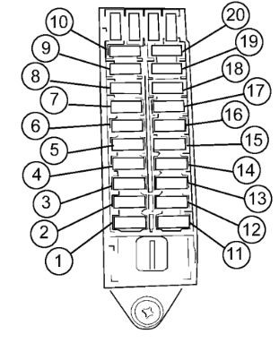
1— 5 Amp—Radio And Monitor Controller Backup
2— 5 Amp—Pump And Valve Controller
3— Not Used
4— 10 Amp—Solenoid
5— 5 Amp—Switch Panel
6— 5 Amp—Engine Control Unit (marked Pow. On)
7— 5 Amp—Air Conditioner And Heater (marked Aircon)
8— 5 Amp—Optional
9— 10 Amp—Optional
10— 5 Amp—Optional
11— 20 Amp—Work And Drive Lights (marked Lamp)
12— 10 Amp—Windshield Wiper And Washer
13— 20 Amp—Air Con And Heater (marked Heater)
14— 10 Amp—Horn
15— 5 Amp—Radio
16— 10 Amp—Lighter
17— 5 Amp—Dome Light (marked Room Lamp)
18— 10 Amp—Aux
19— 5 Amp—Propel Alarm
20— 20 Amp—Start Aid (optional) (marked Glow Relay)