
Claas LEXION 600 - 510 Fuse box diagram & Relay
Claas: 589 00017, 586 00917, 585 00357, 584 02255, 583 00867.
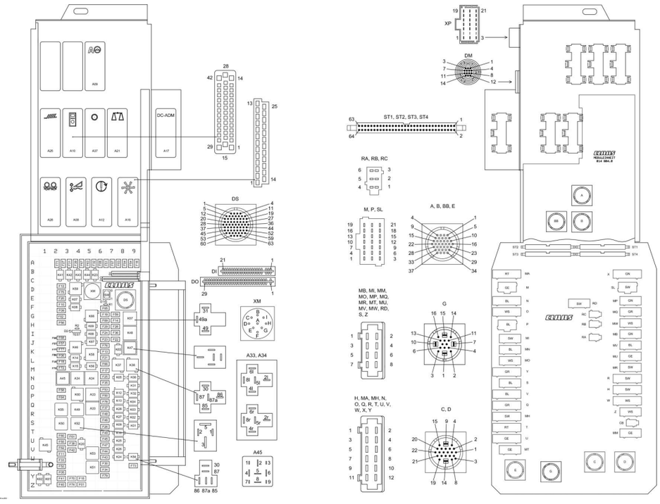
Modules
A08 AUTO LOOP Module (CAC)
A09 AUTOPILOT module
A10 On-board informant module (BIF/CAB)
A12 Speed control module (DZW)
A16 Reel control module (HAS)
A17 Engine adaptation module (ADM)
A21 Quantimeter module (LEM)
A25 Sieve adjustment module
A28 Distribution fan module (VGS)
A33 "Sidefinder" module
A34 Grain tank module
A37 Electro-Hydraulic Circuit Module (EHS)
A45 Traction hydraulic brake throttle module (HBM)
Electronic components
DI Diode Signal Device Board
D0 Circulation Block Valve Diode Board
DS Diagnostics (63 poles) VIA
ST1 Connecting cable (flat)
ST2 Connecting cable (flat)
ST3 Connecting cable (flat)
ST4 Connecting cable (flat)
Fuse
F1 Headlight switching circuit Z 4
F2 Sieve adjustment module, 12 V control G 2
F3 CAN bus connection, loss monitor A 7-8
F4 +12 V electronics A 8
F5 12V air conditioning fan X-Y 2
F6 Reserved (MU plug) K-L 2
F7 CAC A 7 module
F8 Reel module A 6
F9 Quantimeter F 2
F10 Quantimeter F 2
F11 Work lamp inside V-W 2
F12 Work light relay C-D 2
F13 Cigarette lighter K 6
F14 Seat socket G-H 7
F15 Dipped beam/high beam Y 4
F16 12V CAB/DZW A 9
F17 Plus electronics RIO M 6
F18 Header Quick Stop L 2
F19 Engine speed switch G 6
F20 All-wheel drive switch, 12 V E 2
F21 Threshing unit relay L 6
F22 Threshing unit ON. I-J7
F23 Hazard light switch 30 I-J 6
F24 Hazard light switch 15 I 6
F25 Fan speed relay N 6
F26 Reel control S 6
F27 Upper sieve/lower sieve A 2-3
F28 Autopilot switch H 7
F29 Travel lever limit switch, 12 V H 6
F30 Stop light switch, 12 V / grill light Mill W-X 6
F31 Rotary switch, 12 V A 3
F32 12V, IMO system A 5
F33 A/C relay W 2
F34 Engine ignition X 6
F35 Header folding N-O 6
F36 Grain tank extension I 7
F37 12V Grain Tank Drive Q 6
F38 Working light U 3
F39 Chopper key switch I/O A 4
F40 Vehicle lighting switch 12 V Z2
F41 Rotating beacon Y 2
F42 12V horn/windshield washer V 3
F43 Positioning lamp left W 6
F44 Position lamp right V 6
F45 High beam relay left U 6
F46 Left dipped beam relay S 6
F47 High beam relay right U-V 6
F48 Low beam relay right R 6
F49 Table movement T 6
F50 Grain tank extension P 6
F51 Ignition diagnostic plug A 6
F52 Instrument lighting X 2
F53 Illumination of waste product O 6
F54 VGS Module/Autopilot A 9
F55 Working light switch U 2
F56 Spare module H 2
F57 Spare module J 2
F58 Reserved (plug H) O 2
F59 Engine diagnosis G 7
F60 12V ND/HD T-U 2 sockets
F61 Sidefinder T-U 3 module
F62 AS relay, outer guard V 2
F63 12 V, power supply for potentiometers A 5
F64 12 V speed sensors P 2
F65 Backup relay 40 A, 12 V/30 A F 6
F66 12 V RIO STB / radial spreader L 6
F67 RIO, rotor flaps/rotor variator A 4
F68 AS, wheel position I-J 2
F69 12 V, refrigerator socket G-H 6
F70 Ignition key input fuse Y 3
F71 Sieve adjustment module, 12 V supply A 2
F72 MINI ECU M 2
F73 AS, stubble lighting X 9
F74 12 V DC radio positive / radiotelephone Z 3
F75 Ignition, gear control D 2
F76 Maintenance headlight J 6
F77 Plus electronics attachment K 2
F78 DC diagnosis KL.15 P-Q 6
F79 VCU KL.30 Y 6
Relay
K1 Reel lift S 9
K2 Reel lowering R-S 9
K3 Reel forward Q-R 9
K4 Reel back P-Q 9
K5 Raise header N 7-8
K6 Header lower N 9
K7 Lateral header adjustment left E 3-4
K8 Lateral adjustment header right F 3-4
K9 Move table forward S 7-8
K10 Move table back T 7-8
K12 Travel lever zero position P 7-8
K13 Threshing unit 0-I P-Q 7-8
K14 Threshing unit 0-I L 3-4
K15 Header quick stop L-M 3-4
K20 Main lighting relay U-V 4
K23 LiMa B-C 5
K24 A/C relay W 7-8
K25 High beam relay left U 7-8
K26 High beam relay right V 7-8
K27 Left dipped beam relay R-S 7-8
K28 Low beam relay, right Q-R 7-8
K31 Raise grain tank extension O 9
K32 Remove grain tank extension P 9
K37 Fan speed - L-M 7-8
K38 Fan speed + L-M 8-9
K41 Upper sieve movement - B-C 2
K42 Upper sieve movement + B-C 3
K43 Lower sieve movement - B-C 4
K44 Lower sieve movement + B-C 5
K45 Working light U-V 1
K46 Maintenance headlight J-K 3-4
K47 Breaker relay, USA J-K 8-9
K48 Relay-breaker, Europe I 8-9
K49 Main road traffic relay Q-R 4
K50 Work lamp relay S 2
K51 Relay 15 X 5
K52 Ignition relay 15a S 4
K53 Start relay V-W 5
K54 Stubble lighting W 9
K55 Work lamp relay Q-R 2
K56 Plus electronics L-M 5
K57 Pulse transmitter G-H 8-9
K58 Relay Lima K-L 5
K59 Work light relay D 3-4
K60 AS, wheel position O-P 4
K61 Flashing beacon Y-Z 1
K62 Flashing beacon, grain tank 70% Y-Z 1
K63 Fan speed relay J-K 7-8
K66 Backup relay 40 A G 5
K67 Spare relay J 5
K68 Reserve relay I 5
K69 Backup relay H 5
Phil Johnson (Friday, 29 September 2023 05:47)
CLASS Service Manuals, Fault Codes and Wiring Diagrams