
JCB 214e, 214, 215, 217 Fuse box diagram & Relay & EWD
JCB 3CX, 4CX, 214e, 214, 215, 217 & VARIANTS Backhoe Loader From M/c No. 930000 Onwards From M/c No. 903000 Onwards (USA) Fuses and Relays / Wiring diagrams
Always replace fuses with ones of correct ampere rating to avoid electrical system damage.
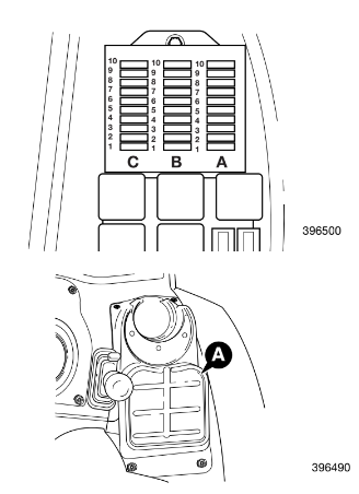
The relays and fuses are located in the side console underneath cover A.
If a fuse melts, find out why and rectify the fault before fitting a new one. The fuses are identified using column letters (A, B and C) and row numbers (1 to 10). Note that all the fuses are shown (including optional equipment fuses). Your machine may not be equipped with all the fuses shown.
Machines up to serial no. 933756
COLUMN ‘A’ Fuse Rating
1 Hydraulic auxiliary 10 Amp
2 Fuel pump solenoid (engine stop) 5 amp
3 Direction indicators 7.5 amp
4 Steer mode proximity switch 7.5 Amp
5 Gearbox control, Transmission 10 Amp
6 Spare
7 Brake lights 5 Amp
8 4 wheel drive (automatic brakes) 3 Amp
9 Left hand side lights 5 Amp
10 Right hand side lights 5 Amp
COLUMN ‘B’
1 Instruments, Buzzer 5 Amp
2 Front horn, Front washer/wiper 15 Amp
3 Rear horn 7.5 Amp
4 Heated seat, Cigar lighter, Face level fan 15 Amp
5 Rear wiper/wash 10 Amp
6 Brake switch 10 Amp
7 Return to dig enable 5 Amp
8 Rear working lights 25 Amp
9 Headlights 20 Amp
10 Front working lights 25 Amp
COLUMN ‘C’
1 Lights 7.5 Amp
2 Hazard light 15 Amp
3 Beacon, Interior light 10 Amp
4 Radio 5 Amp
5 Thermostart 20 Amp
6 Heater 30 Amp
7 Ignition relay coils 3 Amp
8 Main beam 15 Amp
9 Fog light 3 Amp
10 Dip beam 15 Amp
Machines from serial no. 933757
COLUMN ‘A’ Fuse Rating
1 Hydraulic auxiliary 10 Amp
2 Fuel pump solenoid (engine stop) 5 amp
3 Direction indicators 7.5 amp
4 Steer mode proximity switch 7.5 Amp
5 Transmission 10 Amp
6 Gear select / Forward Reverse 3 Amp
7 Transmission 10 Amp
8 Brake lights 7.5 Amp
9 Left hand side lights 5 Amp
10 Right hand side lights 5 Amp
COLUMN ‘B’
1 Instruments, Buzzer 5 Amp
2 Front horn, Front washer/wiper 15 Amp
3 Rear horn 7.5 Amp
4 Heated seat, Cigar lighter, Face level fan 15 Amp
5 Rear wiper/wash 10 Amp
6 Brake switch 10 Amp
7 Return to dig enable 5 Amp
8 Rear working lights 25 Amp
9 Headlights 20 Amp
10 Front working lights 25 Amp
COLUMN ‘C’
1 Lights 7.5 Amp
2 Hazard light 15 Amp
3 Beacon, Interior light 10 Amp
4 Radio 5 Amp
5 Thermostart 20 Amp
6 Heater 30 Amp
7 Ignition relay coils 3 Amp
8 Main beam 15 Amp
9 Fog light 3 Amp
10 Dip beam 15 Amp
Fuses and Relays (continued)
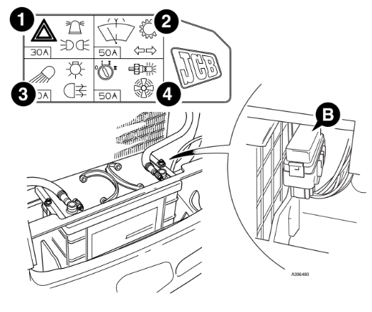
Link Box Fuses
To further protect the machine wiring harnesses and electrical circuits, a fuse link box is fitted to the battery, as
shown at B. Remember to check the main circuit fuses as well as the link box fuses shown on this page.
1 Hazard warning lights, Beacon, Lights 30 Amp
2 Wash/Wipe, Transmission, Indicators 50 Amp
3 Work lights, Fog Lights, Brake lights 50 Amp
4 Ignition, Heater, Thermostart 50 Amp
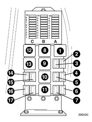
Relays
4 speed Powershift / Synchro Shuttle The relays listed below are located in the side console underneath cover A.
1 Ignition 1
2 Hammer
3 Auxiliary (jaw bucket)
4 Main lights
5 Engine run
6 Hydraulic speed control (HSC)
7 Buzzer (from serial no. 933757 only)
8 Buzzer
9 Ignition 2
10 Front working lights
11 Rear working lights
12 Direction indicator
13 Neutral start
14 Rear horn
15 Parking brake warning light
16 Air conditioning compressor
17 Parking brake (from serial no. 933757 only)
The relays listed below are located in the front console as shown at C.
FD1 Forward HI/LO
FD2 Forward
FE1 Reverse HI/LO
FE2 Reverse
FF1 Interlock
FF2 Drive
FG1 Blank
FG2 Transmission dump
FH1 Auto 2WD
FH2 4WB

6 speed Powershift (Shiftmaster)
The relays listed below are located in the side console underneath cover A.
1 Ignition 1
2 Hammer
3 Auxiliary (jaw bucket)
4 Main lights
5 Engine run
6 Hydraulic speed control (HSC)
7 Buzzer
8 Buzzer
9 Ignition 2
10 Front working lights
11 Rear working lights
12 Direction indicator
13 Neutral start
14 Rear horn
15 Parking brake warning light
16 Air conditioning compressor
17 Parking brake
The relays listed below are located in the front console as
shown at D.
FG1 Reverse Alarm
FG2 Transmission dump
FH1 2WB
FH2 Brake lights
Note: Relay base positions may vary from those shown at D.
Compare wire numbers on the relevant front consloe
harness drawing to confirm relay identification
Wiring diagrams
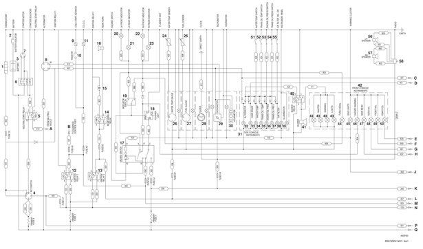
Circuit Schematic - Basic Machine
The basic circuit shows a standard machine. The remaining pages in section C/4 show machine circuits that differ from the
‘basic’. Note that ONLY the differences are shown.
Main Components:
1 Thermostart
2 Battery Isolator
3 Battery
4 Starter Switch
5 Neutral Start Relay
6 Starter Solenoid
7 Starter Motor
8 Alternator
9 Cold Start Advance Solenoid
10 Cold Start Advance Switch
11 Engine Shut-Off Solenoid (ESOS)
12 Ignition Relay ‘1’
13 Ignition Relay ‘2’
14 Rear Horn Relay
15 Rear Horn Switch
16 Rear Horn
17 Hazard Warning Switch
18 Indicator Flasher Unit
19 Direction Indicator Switch
20 LH Front Indicator
21 LH Rear Indicator
22 RH Front Indicator
23 RH Rear Indicator
24 Engine Coolant Temperature Sender
25 Fuel Gauge Sender
26 Engine Coolant Temperature Gauge
27 Fuel Gauge
28 Clock
29 Tachometer
30 Hourmeter
31 Side Instrument Console
32 Alternator Warning Indicator Light
33 Parking Brake Indicator Light
34 Engine Coolant Temperature Indicator Light
35 Transmission Oil Temperature Indicator Light
36 Engine Oil Pressure Indicator Light
37 Transmission Oil Pressure Indicator Light
38 Air Filter Blocked Indicator Light
39 Panel Illumination
40 Warning Buzzer Relay
41 Warning Buzzer
42 Front Instrument Console
43 Master Warning Lights
44 Turn Signal Indicator
45 Side Lights Indicator
46 Hazard Warning Indicator
47 Main Beam Warning Indicator Light
48 Rear Working Light Indicator
49 Front Working Light Indicator
50 Rear Fog Light Indicator
51 Engine Coolant Temperature Switch
52 Transmission Oil Temperature Switch
53 Engine Oil Pressure Switch
54 Transmission Oil Pressure Switch
55 Air Filter Restriction Switch
56 LH Speaker
57 RH Speaker
58 Radio (if fitted)
Connections:
A From A on page C/4-5 and C/4-13 as applicable
B To B on page C/4-5
C To C on page C/4-4
D From D on page C/4-5 and C/4-13 as applicable
E From E on page C/4-4
F From F on page C/4-4
G From G on page C/4-4
H From H on page C/4-4
J From J on page C/4-4
K To K on page C/4-4
L To L on page C/4-4 and C/4-8, and C/4-13 as applicable
M To M on page C/4-8 and C/4-13 as applicable
N To N on page C/4-4
P To P on page C/4-4
Q To Q on page C/4-4
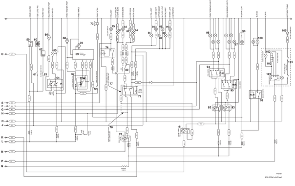
Main Components:
59 Cigar Lighter
60 Face Level Fan
61 Face Level Fan Switch
62 Heated Seat
63 Heated Seat Switch
64 Rear Washer/Wiper Switch
65 Rear Wiper Motor
66 Rear Washer Motor
67 Front Washer/Wiper Switch
68 Front Washer Motor
69 Front Wiper Intermittent Electronic Control Unit
70 Front Wiper Motor
71 Head Light Flasher Switch
72 Front Horn Switch
73 Front Horn
74 Rear Fog Light Switch
75 Rear Fog Light
76 Removed For Territories - Italy, Germany
77 Fitted For Territories - Italy, Germany
78 Road Lights Relay
79 Road Lights Switch
80 Head Light Dip Switch
81 LH Main Beam Light
82 RH Main Beam Light
83 LH Dip Beam Light
84 RH Dip Beam Light
85 LH Tail Light
86 LH Side Light
87 Socket (Dipper Light)
88 Number Plate Light
89 RH Tail Light
90 RH Side Light
91 Engine Running Relay
92 Front Working Lights Relay
93 Rear Working Lights Relay
94 Front Working Lights Switch
95 Rear Working Lights Switch
96 Front Working Lights
97 Rear Working Lights
98 Cab Interior Light/Switch
99 Beacon Switch
100 Beacon
101 Heater Switch
102 Heater Motor
103 Heater Resistor
104 Air Conditioning Pressure Switches
105 Air Conditioning Compressor Solenoid
Connections:
C From C on page C/4-1
E To E on page C/4-1
F To F on page C/4-1
G To G on page C/4-1
H To H on page C/4-1
J To J on page C/4-1 and C/4-9
K From K on page C/4-1
L From L on page C/4-1
N From N on page C/4-1
P From P on page C/4-1
Q From Q on page C/4-1
R To R on page C/4-9
Fuses:
A1 - A10
B1 - B10
C1 - C10
Paul Kasperski (Wednesday, 19 July 2023 20:23)
Thanks for the info.