
John Deere 7630, 7730, 7830 & 7930 Fuse box diagram & Relay

Load cell fuses John Deere 7630, 7730, 7830 & 7930
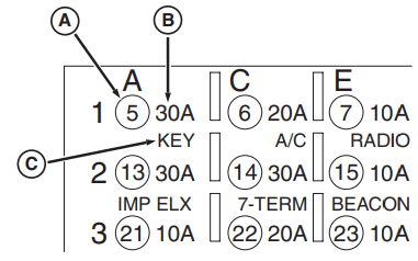
The picture on the right shows how to Interpret the diagrams of the loading center.
A—Home location of padoxpanels
B—PedoxPanel Pasmap
C—Using/Optioning Preexposure Panels
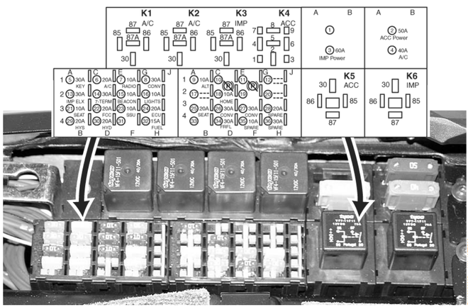
1—Not used
2—Boardapparatypa
3—Power supply for working equipment
4—Fan motor
5—Ignition key
6—ATC and blower fan
7—Radio, steering column, horn, clock and dome light non-switchable power
8—Right connector block, electrical outlet and cigarette lighter - battery powered
9—Generator
10—Reserved - used for IVT only
11—Reserved - used for IVT only
12—Not used
13—ELX and work equipment controllers
14—Auxiliary relay/7-pin
15—Rotating beacon and powered mirrors
16—Hazard and lighting switch
17—Not used
18—Return Mode - IVT only
19—Not used
20—Not used
21—Driver presence sensor
22—Cab controller
23—SSU Power
24—Engine control unit (ECU)
25—Seat adjusters
26—Commercial band radio, CB radio, field office, left junction block - acc. ignition key position
27—Right connector block, accessories
28—Reserved
29—Hydraulic regulator (optional)
30—SCU
31—Not used
32—Fuel electric pump
33—Not used
34—Front field lights on the roof (if equipped)
35—Reserved
36—Reserved
K1—AC relay, ATC
K2—AC relay, blower motor
K3—Not in use
K4—Not in use
K5—Onboard equipment relay
K6—Power for work equipment
Parking brake release (IVT transmission) John Deere 7630, 7730, 7830 & 7930

A—Plastic Fuse Disconnect
B—Fuse 10 (Location)
C—Fuse 11 (Location)
D—Fuse 18 (Location)
E—Fuse 24 (Location)
1. Lock the tractor tires.
2. Make sure the ignition key is in the OFF
NOTE: Moving fuses allows you to rotate engine crankshaft without launch it.
3. Remove cover to access to the guards. (See Access to the fuses and relays in the section Maintenance - Electrical system.)
4. Remove the plastic disconnector (A) from fuse no. 10 (B) and fuse
11 (C) and remove the fuses.
5. Replace fuse no. 18 (D) fuse no. 10, a fuse no. 24
(E) - in place of fuse no. 11.
6. Turn the ignition key to the “RUN” position (not “START”). The signal lamp TO will be blink. After five seconds signal lamp The STOP button will also start flashing.
7. Turn the ignition key to position “START” and crank the engine for
10 - 15 seconds. Let go of the key and make sure that it is set to the RUN position.
8. If the indicator lights are flashing instead parking brake and stop lamps ENGINE, this means that not enough in the hydraulic system pressure to unlock
parking brake. Repeat step 6 more up to two times. If the signal lamp THEN does not blinking, contact your local dealer of John Deere.
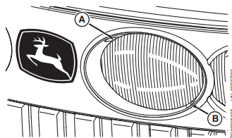
Replacement of projector lamps on the front grille - standard lighting
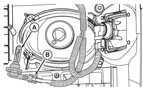
1. Raise the hood.
2. Disconnect the harness connector (B).
3. Turn the bulb holder (A) counterclockwise arrows about 1/4 turn and remove it.
4. Install the lamp socket in reverse order withdrawal.
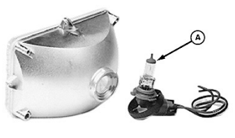
WARNING: In halogen lamps (A) gas is under pressure. Wrong Handling the lamp may cause a burst flasks and scattering of fragments. Bo avoidance trauma:
• Hold the lamp by the base. Do not allow oil getting on the lamp; use mittens, so as not to get burned on the glass.
• Turn off the power to the lamps and allow them to cool down with a replacement. Do not turn on until replacement lamps are not produced.
• Use the means of protecting organs vision.
• Do not scratch or break the lamp. hold in a cyx place.
• Put the old lamp in a case from new and dispose of properly. Keep out of reach of children.
Headlight adjustment John Deere 7630, 7730, 7830 & 7930
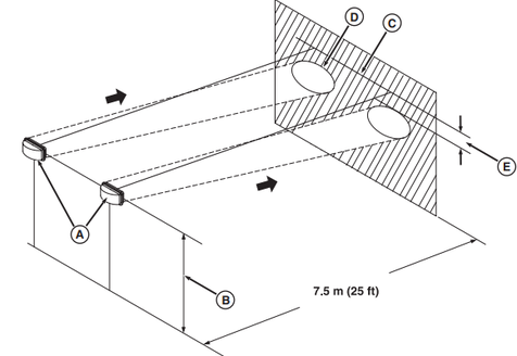
A—Headlights
B—Headlight center to ground
C—Horizontal line on the wall
D—borders of bright spot
E—10% of distance (B)
1. Park the tractor on a level surface so that the headlights/work lights (A)were within 7.5 m (25 ft) of vertical wall.
2. Measure the distance (B) from the center of the front headlights to the ground.
3. Draw a horizontal line (C) on the wall on the same distance (B) from the ground.
4. Set the headlights / work lights to low light and observe the illuminated areas on wall.
5. Adjust the headlights/work lights like this in such a way that the upper border of the illuminated zone (D) was at least one tenth of the distance (B) below the line (C).
Turn the screw (A) so as to set headlights inside in the direction uppx.
Turn the screw (B) to move fary out and down.