
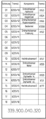
Fendt 300 Vario fuse box diagram and Relay

FENDT 309 Vario COM III from Chassis-No: 336 .. 1001-
FENDT 310 Vario COM III from Chassis-No: 337 .. 1001-
FENDT 311 Vario COM III from Chassis-No: 338 .. 1001-
FENDT 312 Vario COM III from Chassis-No: 339 .. 1001-
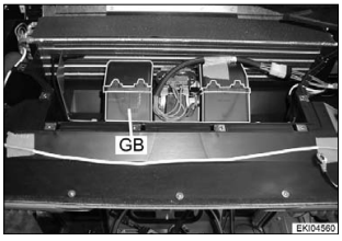
Fuse holder X050, X051 and A013
Danger: Use only genuine fuses! Electrical system will be destroyed if fuses with too high ratings are used. Beware of fire risk!
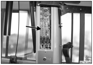
Fuse holder (X050, X051) Fendt 300
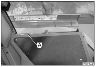
Fuse holder (A013) Unscrew cover panel. Fendt
Fuse holder X050, X051 and A013
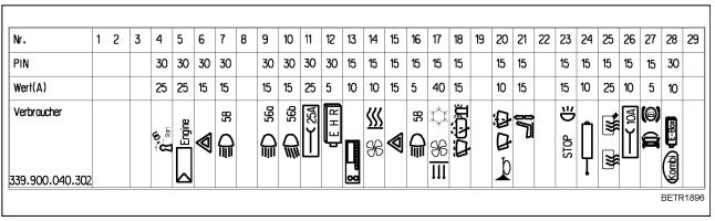
Fuse holder X050
|
Fuse no. |
Pin |
Rating (A) |
Consumer |
|
1 |
- |
- |
- |
|
2 |
- |
- |
- |
|
3 |
- |
- |
- |
|
4 |
30 |
25 |
Heater plug starter switch position ON |
|
5 |
30 |
25 |
Control module |
|
6 |
30 |
15 |
Hazard warning lights pushbutton |
|
7 |
30 |
15 |
Headlights pushbutton |
|
8 |
30 |
10 |
- |
|
9 |
30 |
15 |
Relay no. 56a (headlights) |
|
10 |
30 |
15 |
Relay no. 56b (dipped beam) |
|
11 |
30 |
25 |
Socket 25 A |
|
12 |
30 |
5 |
EPC |
|
13 |
15 |
10 |
Radio |
|
14 |
15 |
25 |
Heater switch |
|
15 |
15 |
15 |
Hazard warning lights pushbutton |
|
16 |
15 |
5 |
Headlights pushbutton |
|
17 |
15 |
40 |
Blower switch |
|
18 |
15 |
15 |
Front wipers pulse generator |
|
19 |
15 |
10 |
- |
|
20 |
15 |
10 |
Steering column switch (multifunction switch) |
|
21 |
15 |
15 |
Driver seat, seat heating |
|
22 |
- |
- |
- |
|
23 |
15 |
15 |
Brake relay |
|
24 |
15 |
10 |
3rd hydraulic circuit relay |
|
25 |
15 |
25 |
Rear window heater, mirror heater |
|
26 |
15 |
10 |
Socket 10 A |
|
27 |
- |
- |
- |
|
28 |
- |
- |
- |
|
29 |
15 |
25 |
not assigned |
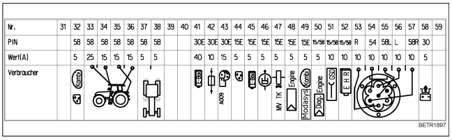
Fuse holder X051

Fuse holder X050, X051 and A013

Fendt 300 Vario Relay
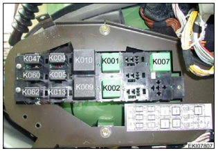
K001 = Relay, +UB 15 (switched positive)
K002 = Relay, +UB 58 (lighting)
K004 = Relay, 56a (main beam)
K005 = Relay, 56 b (dipped beam)
K007 = Relay, brake
K009 = Relay, windscreen wiper
K010 = Relay, direction indicator controller
K013 = Relay, 3rd hydraulic circuit (optional extra)
K047 = Relay, hydraulic trailer brake (Italy)
K060 = Relay, clutch / turboclutch
K062 = Relay, EDC

K063 = Relay, heating flange
Left side of engine on intake pipe
K064 = Battery disconnect relay
Right entrance step
Remove panel
Note:
Battery disconnect relay is screwed directly on
the battery, not shown in picture
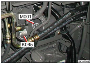
K065 = Relay, starter
Left side of engine in front of the starter
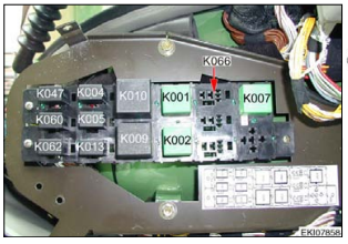
K066 = Relay, compressed air pilot control
In cab on right mudguard
Remove control console

In windscreen:
M002 = Front wiper motor
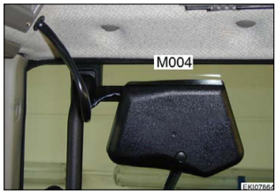
In rear window:
M004 = Rear wiper motor
Note:
Test rear wiper motor in same manner as front
wiper motor M002.

M003 = Wiper pump, front
M005 = Wiper pump, rear
on left rear mudguard
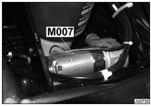
M007 = seat adjustment motor (compressor)
On driver seat spring unit:

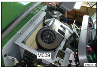
M009 = Heater blower
At top of steering column
Remove A007 instrument cluster, panel
and air duct. Place heat exchanger to the
side
M014 = Roof blower (infinitely adjustable)
(optional)
On top under the cab roof
M018 = Roof blower levels 1, 2 and 3 for
air-conditioning .
On top under the cab roof
Remove roof cover from cab, then
unscrew plastic cover
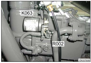
R002 = Heating flange
Left side of engine on intake pipe