
Deutz Fahr 120 130 150 Fuse box Diagram & Relay location
Deutz Fahr 120 130 150 150.7 165.7
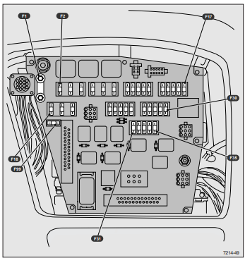
NOTE: Use only original fuses. The use of incorrect fuses may result in irreparable damage to the system.
F1 = main fuse; 100 Amp
F2 = flashing light, front wiper; 30 Amp
F3 = fan, air conditioning system; 30 Amp
F4 = rear work lights (on the right and left side of the tractor); thirty ampere - see also F10 F5 = not used
F6 = front work lights; 30 amps - see also F10 F7 = radio, radiotelephone, clock, roof clamp 15; 20 amps
F8 = clock, cab lighting, radio, radiotelephone, roof clamp 30; 5 Amp.
F9 = low/high beam headlights, switch indicator lights; 7.5 ampere - see also F21/F22/F23
F10 = on-board computer - switch illumination: backup headlights, front working spotlight above turn signal, front working
floodlight on the roof of the cab, rear working searchlight, control drive, double drive; 7.5 Amp
F11 = brake lights, RL8; 15 amp
F12 = Front washer/wiper - horn; 15 Amp
F13 = Dual drive - differential lock; 15 Amp
F14 = front work light (lower); 15 Amp
F15 = direction indicator; 15 Amp.
F16 = INFOCENTER system, mode/radar sensor, rear PTO, display gearboxes, air conditioning compressor, indicators switch: rear wiper, flashing light; 3 Amp
F17 = front axle with suspension; 7.5 amps - see also F11 F18 = cigarette lighter, rear 1-pole connector; 30 Amp.
F19 = Main plug; 30 Amp.
F20 = parking lights on. switch, low beam headlights; 30 amps - see also F24/F25 F21 = upper left dipped beam; 7.5 amps - see also F23/F9
F22 = Upper right low beam, 7.5 amps - see also F23/F9
F23 = low beam headlights; 15 amp
F24 = Dashboard lighting, left position lamps, illumination lamp number plate, rear left position light, connector for trailer connection,
terminal 58 left; 7.5 amps - see also
F20 F25 = right position lamp, right license plate lamp, rear right lights, trailer socket, clamp 58 on the right; 7.5 Amp. - see also
F20 F26 = flashing light alarm; 15 Amp
F27=INFOCENTER, POWERSHIFT; 1 Amp
F28 = block active via relay 13, driver's seat; 15 Amp
F29 = PTO drive - PTO probe; 7.5 Amp
F30 = engine shutdown solenoid, electronic speed control engine (EMR); 7.5 Amp
F31 = lower left low beam, 7.5 amp - see also F23 F32 = lower right low beam headlight; 7.5 Amp. - see also F23 F33 = bottom/top
high beam headlights; 15 amps - see also F20 F34 = hoist AGROTRONIC; 7.5 Amp
F35 = POWERSHIFT system clamp 15; 7.5 amps
F99 = 4th fan speed - in the fan control unit; 30 amps (Maxi Fuse)

Relays and their functions
1 = diagnostic connector
RL 1 = clip 15; 40 amps
RL 2 = rear work lights; 40 Amp
RL 3 = front work lights; 40 Amp.
RL 4 = front wiper; 10 Amp
RL 5 = clearance lamp; 10 Amp
RL 6 = switching of upper/lower dipped beam headlights; 10 Amp
RL 7 = low beam headlights; 10 Amp
RL 8 = brake light; 10 Amp
RL 9 = double actuator solenoid valve; 10 Amp
RL 10 = driving lights; 10 Amp
RL 11 = upper/lower high beams; 10 Amp.
RL 14 = direction indicator; flashing hazard warning lights; 10 Amp
NOTE: Use only original fuses. The use of incorrect fuses may result in irreparable damage to the electrical system.

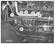
1 - Starter relay
2 - Condenser fan air conditioning systems air
3 - Front work lights
4 - Fuse front working spotlight
5 - Fuse fan
6 - System control unit preheating 100 amps
Fuse box AGROTRON 120-130-150
On the left side of the engine, behind a protective metal partition, engine heating system control unit and relay installed engine electrical system.

1 - System control unit preheating
2 - Condenser fan air conditioning systems air
3 - Front work lights
4 - Starter relay
5 - Fuse F 100 30 A condenser fan air conditioning systems air
6 - Fuse front working spotlight
DANGER: Battery fumes, if present open flames can cause an explosion. In this regard, in the immediate vicinity of the battery is prohibited use sources of sparks and devices with an open flame. Storage and battery charging should be carried out in a well ventilated area Avoid acid contact with skin and clothing
Cleaning the Radar Sensor
In order to ensure
correct execution
measurements, the front of the sensor
must be completely clean.
To clean the sensor, use
clean water
Replacing incandescent lamps
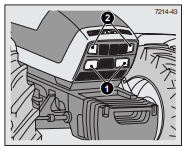
Front spotlights
1 = Front spotlights
H4 12V 60/55W
2 = Work lights
ECE 37 HB3 2V 55W

Roof front spotlights
cabins*
1 = Working spotlight
H30 12V 55W

Rear spotlights
1 = Work lights
H3 12V 55W
2 = Working light
H3 12V-55W 24V-70W
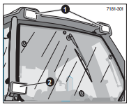
Marker lamps, direction indicators and duplicate headlights *
1 = Marker lamp
DIN 72601-R19/5 12V 5W
2 = Front turn signal
DIN 72601-P25-1 12V 21W
3 = Duplicate headlights *
H4 12V 60/55W
DIN 72601-T8/4 12V 4W

Lantern lamps set
on the hind wings
1 = Turn signal
DIN 72601-P25-1 12V 21W
2 = Brake/rear
marker lights
DIN 72601-P25-2 12V 21/5W

Side panel lighting
management
DIN 72601-K 12V 10W

Cabin interior lighting
DIN 72601-TB/4 12V 4W
Adjusting the headlights when driving on the road Deutz Fahr 120 130 150

To make this adjustment, the tractor must be in the transport condition and be on a horizontal surface with front wheels in the forward position; tire pressure should
correspond to the nominal value. In addition, the tractor must be installed at a distance of 10 m from vertical wall and have low beam headlights on.
1 - Points determined by the projections of the axes of the headlights on the wall
A - Distance between headlights
H - Headlight height
h - Distance of the horizontal axis from the center of the light beam
X - Distance between headlights and wall
For adjustment, use the screws indicated by the arrows in the figure; the light beam of the flashlight can be shifted both vertically and horizontal.
NOTE: To establish points defined by projections axes of the headlights on the wall, it is recommended to bring the tractor closer with the
dipped beam headlights to the wall, mark the centers on the wall, then move the tractor back up to a distance of 10 m from the wall.
Horizontal adjustment
With the headlights on, the distance between the centers of the light beams must correspond to distance A, as shown in the figure.
Headlight adjustment vertically
With the headlights on, the distance h between the lines, limiting the light and dark zones on the wall should be 10 cm as shown in the picture.
Regulation of duplicate headlights

Mount the tractor as indicated for adjusting the headlights (see instructions on previous pages).
Turn on low beam headlights.
A = Distance between headlight centers
3/3 = Headlight center height from the ground
2/3 = Height of border between light and dark zones (2/3 of 3/3 height)
X = Distance of headlights from wall = 10 m
To adjust the backup headlights, use the above distances and sizes.
Lateral regulation
The distance between the centers of light beams on the wall should correspond to the distance A measured on the tractor between headlights
Headlight height adjustment
Install the tractor so that the distance X between the duplicate headlights and a vertical wall was 10 m. Example:
Measure the height of the duplicate headlights from the ground. for example: 2.82 m.
The distance between the lines that bound the light and dark zones
on the wall should be equal to 2/3 of the mounting height of the backup headlights.
Mounting height (2.82 m): 3 x 2 = border between light and dark zone (1.88 m)