
Bobcat 853H S650 Skid-Steer Loader Fuse box diagram & Relay

Bobcat 853, 853H, S650, S150, S175, S185 turbo Fuse box location and diagram
S/N A3NW11001 & Above
Fuse And Relay Location / Identification (Cont’d)
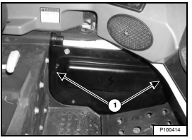
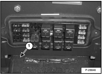
The fuse / relay panels are located behind an access panel near the left foot pedal / footrest. Pull the panel at
each end (Item 1) to remove.
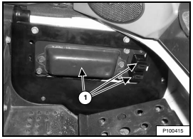
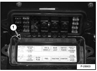
The electrical system is protected from overload by fuses and relays located under three fuse panel covers (Item 1)
Remove the covers to check or replace the fuses. A decal is located inside the access panel to show location and amperage ratings.
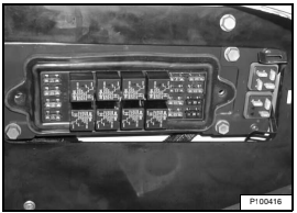
Line up the clips on the back of the access panel with the slots provided and push the panel into place when finished. A locating pin prevents the panel
from being installed upside down. A table is provided with details on amperage ratings and circuits affected by each fuse and relay.
Fuse And Relay Location / Identification (Cont’d)
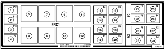
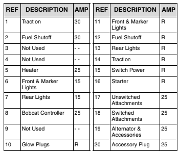
The location and amperage ratings are shown in the table below and on the decal. Relays are identified by the letter “R” in the AMP column.

Bobcat 353 & 853H Fuse box diagram & Relay
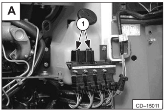
The loader has a 12 volt, negative ground alternator charging system. The electrical system is protected by fuses (Item 1) [A] located in the engine compartment. The
fuses will protect the electrical system when there is an electrical overload. The reason for the overload must be found before starting the engine again.
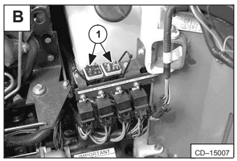
Fuse Location (Standard & BOSS® Option) The electrical system for loaders is protected by eight
fuses located in the fuse block (Item 1) [B]. Remove the fuse block cover to access the fuses.
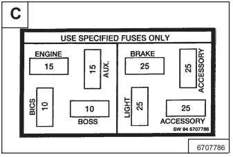
The decal inside the rear door specifies the fuse sizes used in various loader circuits [C].
Bobcat S150 Fuse & Relay
The loader has a 12 volt, negative ground alternator charging system. The electrical system is protected by fuses located in the cab on the steering control panel, and a 100 amp master fuse in the engine compartment on the left side of the engine, under the air cleaner. The fuses will protect the electrical system when there is an electrical overload. The reason for the overload must be found before staring the engine again.
Bobcat S175, S185 turbo Fuse box location and diagram
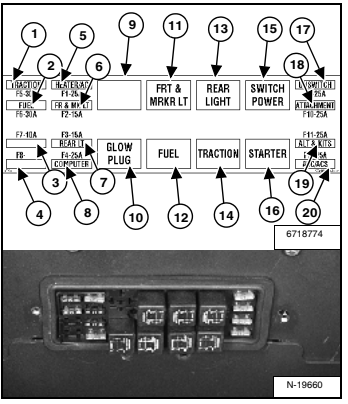
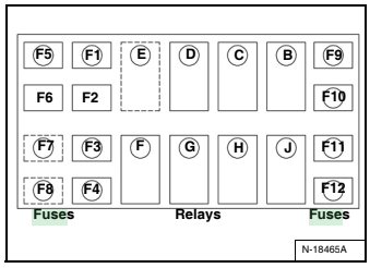
Fuse Location
F1 Heater 25
F2 Front & Marker Lights 15
F3 Rear Lights 15
F4 Bobcat Controller 25
F5 Traction 30
F6 Fuel Shutoff 30
F7 Not Used --
F8 Not Used --
F9 Unswitched Attach. 25
F10 Switched Attach. 25
F11 Alternator & Kits 25
F12 ACS Power 25
Relay Switch Location Remove the cover to check or replace the relays.
REF Description
B Switch Power
C Rear Lights
D Front & Marker Lights
E Not Used
F Glow Plugs
G Fuel Shutoff
H Traction
J Starter