
John Deere 8130, 8230, 8330, 8430 & 8530 Fuse box diagram & Relay
Load Center Fuses and Relays - North America
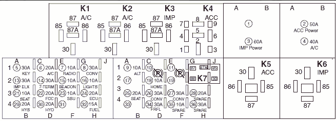
F2 - Aircraft
F3 - Power of working equipment
F4 - Cabin power cable
F5 - Ignition switch
F6 - ATC and blower fan
F7 - Radio, steering column, horn, clock and dome light - non-switchable power
F8 - Right contact block, power socket and cigarette lighter - Battery supply
F9 - Generator
F10 - Reserved - only used for IVTIVT
F11 - Reserved - used only for IVT
F12 - No
F13 - ELX, work equipment controllers
F14 - Light relay outputs
F15 - Flashing beacon and powered mirrors
F16 - Emergency lighting
F17 - Reset mode - IVT only
F18 - Reset mode - IVT only
F19 - No
F20 - No
F21 - Driver presence sensor
F22 - Cabin controller
F23 - Power SSU
F24 - Engine control unit (ECU)
F25 - Seat controller
F26 - Industrial radio, CB radio, field office, left connection block - acc. ignition key position
F27 - Right connector block, accessories
F28 - Reserved
F29 - Hydraulic governor (optional)
F30 - SCU
F31 - No
F32 - Electric fuel pump
F33 - No
F34 - No
F35 - Reserved
F36 - Reserved
FX2-JD Link
FX3 - No
K1 - AC relay, ATC
K2 - Blower fan motor with AC relay current
K3 - No
K4 - No
K5 - Onboard equipment relay
K6 - Power of working equipment
K7 - No
KX2 - Reverse Warning Relay
F46 - Reserve or AutoTrac1
F47 - Left terminal block, field office
F48 - Power socket, right contact block, auxiliary contact block (switchable)
Fuses and load center relays - European version

F2 - Aircraft
F3 - Power of working equipment
F4 - Cabin power cable
F5 - Ignition switch
F6 - ATC and blower fan
F7 - Radio, steering column, horn, clock and dome light - non-switchable power
F8 - Right contact block, power socket and cigarette lighter - battery powered
F9 - Generator
F10 - Reserved - used only for IVT
F11 - Reserved - used only for IVT
F12 - No
F13 - ELX, work equipment controllers
F14 - Light relay outputs
F15 - Flashing beacon and powered mirrors
F16 - Emergency lighting
F17 - Reset mode - IVT only
F18 - Reset mode - IVT only
F19 - No
F20 - No
F21 - Driver presence sensor
F22 - Cabin controller
F23 - Power SSU
F24 - Engine control unit (ECU)
F25 - Seat controller
F26 - Industrial radio, CB radio, field office, left connection block - acc. ignition key position
F27 - Right connector block, accessories
F28 - Reserved
F29 - Hydraulic governor (optional)
F30 - SCU
F31 - Brake relay
F32 - Electric fuel pump
F33 - No
F34 - Headlights at the base of the cab
F35 - Reserved
F36 - Reserved
FX2-JD Link
FX3 - No
K1 - Loader headlights
K2 - Blower fan motor with AC relay current
K3 - No
K4 - No
K5 - Onboard equipment relay
K6 - Power of working equipment
K7 - Brake relay
KX2 - Reverse Warning Relay
F46 - Reserve or AutoTrac1
F47 - Left terminal block, field office
F48 - Power socket, right contact block, auxiliary contact block (switchable)
Location of wiring ground points

Numeric and color codes of wires
Two methods of coding circuits - digital and color.
A three-digit numeric code is used to identify each wire circuit. Given
the code is printed on each wire of the harness at intervals of 25 mm (1 in.). Circuit numbers and related functions are shown below.
000 - 099 Power supply
100 - 199 Lighting
200 - 299 Aircraft
300 - 499 Engine
500 - 699 Transmission
700 - 799 Hydraulics
800 - 899 Weight
900 - 999 Other
The wire insulation colors are determined by the last digit of the wire circuit number. The chain numbers corresponding to the wire colors and the color code are shown below.
XX0 Black White
XX1 Brown White
XX2 Red White
XX3 Orange Black
XX4 Yellow Black
XX5 Dark Green White
XX6 Blue Black
XX7 Violet White
XX8 Gray Black
XX9 White Black
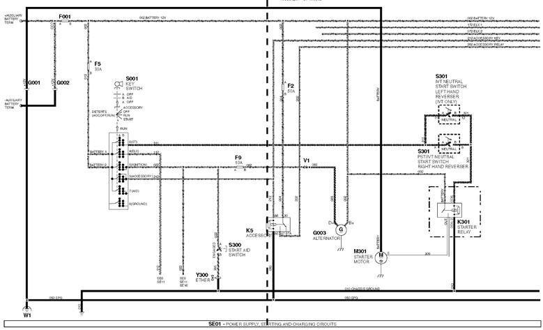
SE01 Power supply, Starting and Charging circuit John Deere 8130, 8230, 8330, 8430 & 8530
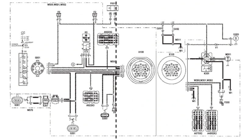
• A570X2 VLC, CCU, PTI or PTP connector (SE11) (W573, W574)
• A922X2 Socket CLC, TEC, TEI (SE6) (W500, W502, W503)
• A922X3 CLC, TEC, TEI (SE6) (W500, W502, W503)
• F001 Main propane breather (SE1)
• F2 Pelebobian appapathy (SE1) (W500, W502, W503)
• F5 Ignition switch (SE1) (W500, W502, W503)
• F9 Alternating current generator (SE1) (W500, W502, W503)
• G001 Battery (SE1)
• G002 Battery (SE1)
• G003 Alternator (SE1) (W300, W301, W302)
• K5 Pelebobian appapathy (SE1) (W500, W502, W503)
• K301 Peak Oil (SE1) (W300, W301, W302)
• M301 Starter (SE1)
• S001 Ignition switch (SE1) (W500, W502, W503)
• S300 Starting aid switch (SE1) (W500, W502, W503)
• S301 Neutral start switch (SE1) (W570)
• V1 AC genepath diode (SE1) (W500, W502, W503)
• W1 Common ground connection point
• W010 Beta-pee loading cable
• W011 Beta-pee cable
• W300 MWPC/2WD Chassis Wiring Harness (Ring Tractors Only)
• W301 ILS Chassis Harness (Ring Tractors only)
• W570 Armrest control box harness (14-pin)
• X100 Cabin rear connector (plug), rear connector shaft (female) (W300, W301, W302, W500, W502, W503)
• X301 Neutral boost switch RHR (W570, W500, W502, W503)
• Y300 Ethiopian Squeak Knee (SE1) (W300, W301, W302)
• 1 Bopt appatip chain