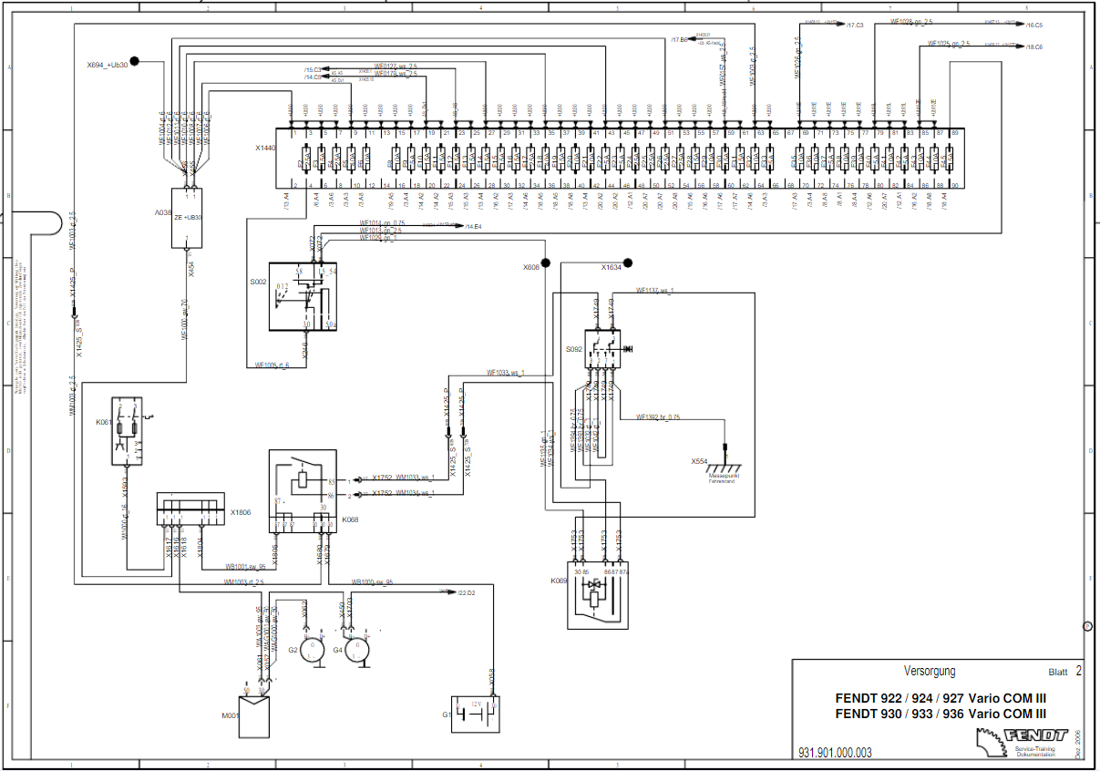
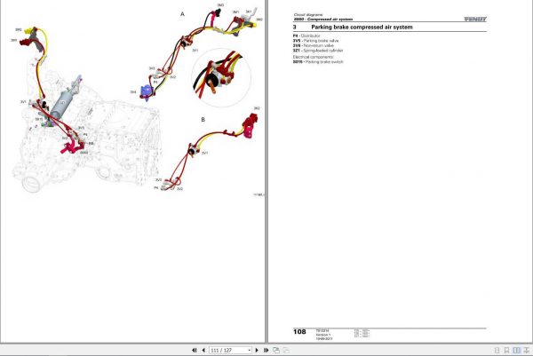
Fendt Electrical Wiring Diagrams
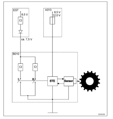
EST - electronic control unit (ECU)
B010 - engine Hall-effect sensor 1 (example)
A013 - fuse board (X200, X201, X202)
STE - control unit
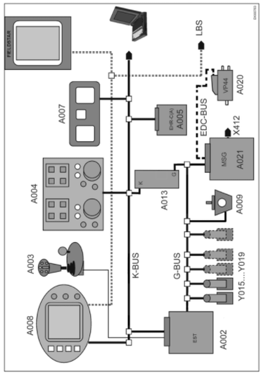
A002 EST Comfort Control Module
A020 Injection Pump VP 44
A003 Joystick
A021 EDC Control Module
A004 Side Console
X412 Diagnostic
A020/A021
A005 EPC Control Module
G-BUS Transmission-BUS
A007 Dashpanel
K-BUS EST Comfort - BUS
A008 Terminal
EDC-BUS EDC-BUS
A009 Transmission Control Module
LBS LBS - Fieldstar (optional)
A013 Fuse Board
Fav 700
Fav 900
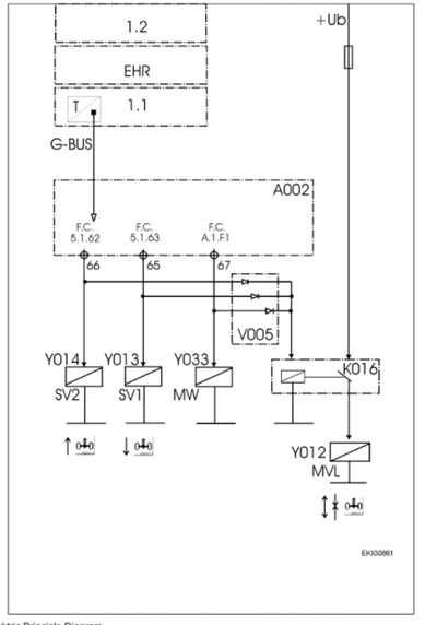
Elektric Principle Diagram
Fav 700
Fav 900
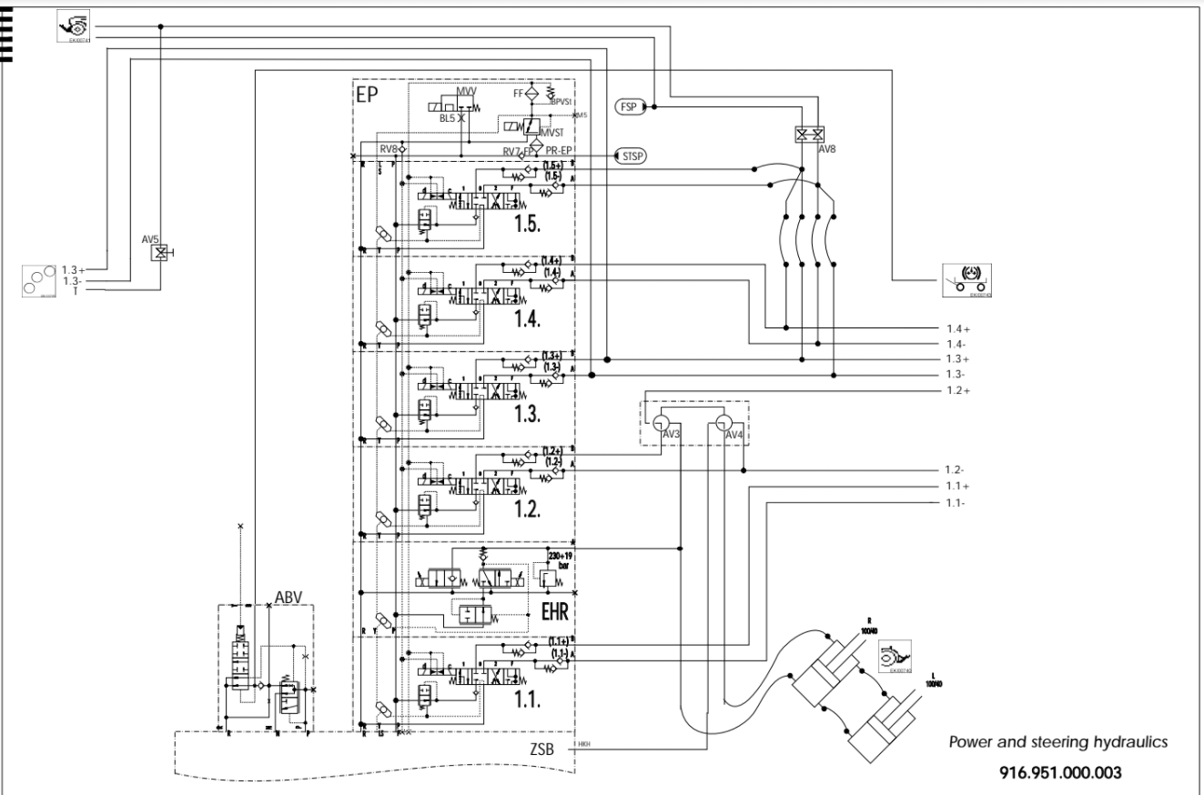
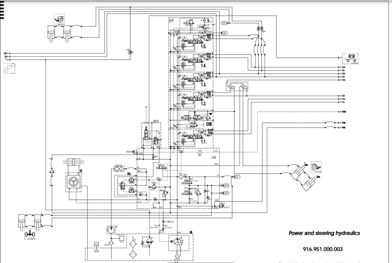
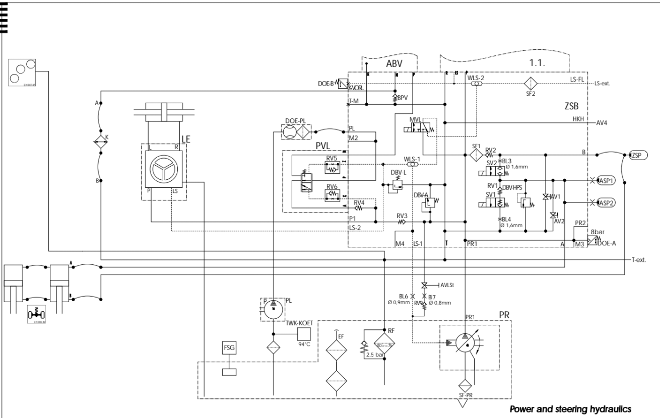
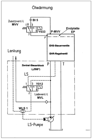
Hydraulic Principle diagram
Remarks to Fav 900: Additional Valve MVV and Orifice Bl5 are integratd within the final Plate.

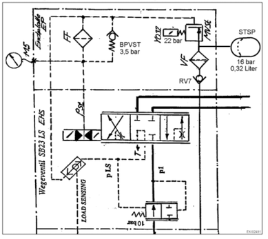
Circuit diagram: end plate - EP with diaphragm accumulator - STSP
EP End plate
FF Microfilter (paper)
RV7 Non-return valve
M5 Pressure-measuring point
VF Prefilter (sintered metal)
T Return flow
STSP Diaphragm accumulator
pSt Control pressure (22 bar)
MVSt Control pressure solenoid valve
PLS Load-sensing pressure
Y032 Control pressure solenoid valve
P1 Pump pressure
Farmer 400
Fav 700
Fav 900
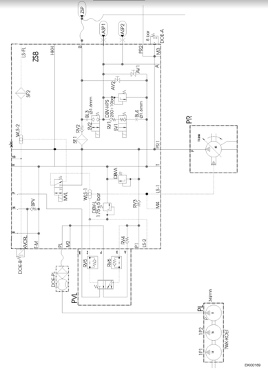
Central control block

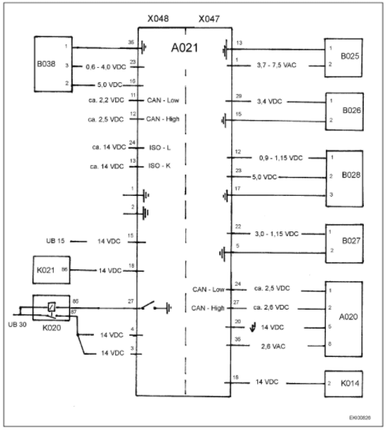
A020 Pump control unit
B038 Accelerator sensor, EDC
A021 EDC control module
K014 Exhaust brake relay
B025 EDC speed sensor
K020 EDC UB 30 relay
B026 Needle motion sensor
K021 Shutoff solenoid valve relay
B027 Water temperature sensor
X047 Engine connector
B028 Intercooler pressure sensor
X048 Body connector
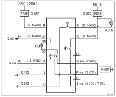
A G002 / G004 - generator indicator D+
X050 Fuse holder 1
D X512 - left engine earthing point links
30 G002 / G004 - generator B+
G Preheating (supply)
FU 80 amp fuse
H Telltale in A007 - display unit
J Y025 - valve, cold-start aid B+ Battery + (generator)
K S002 - switch, ignition (50a) D+ Dynamo + (generator)
L Check (cold-start system, temperature >
glow-stop temperature (2.5°C))
UB15 Switched voltage after battery
(output S002 - switch, ignition)
N,P R001 - heater plug 50a Battery changeover relay, output forstarter control unit
O,R Not assigned
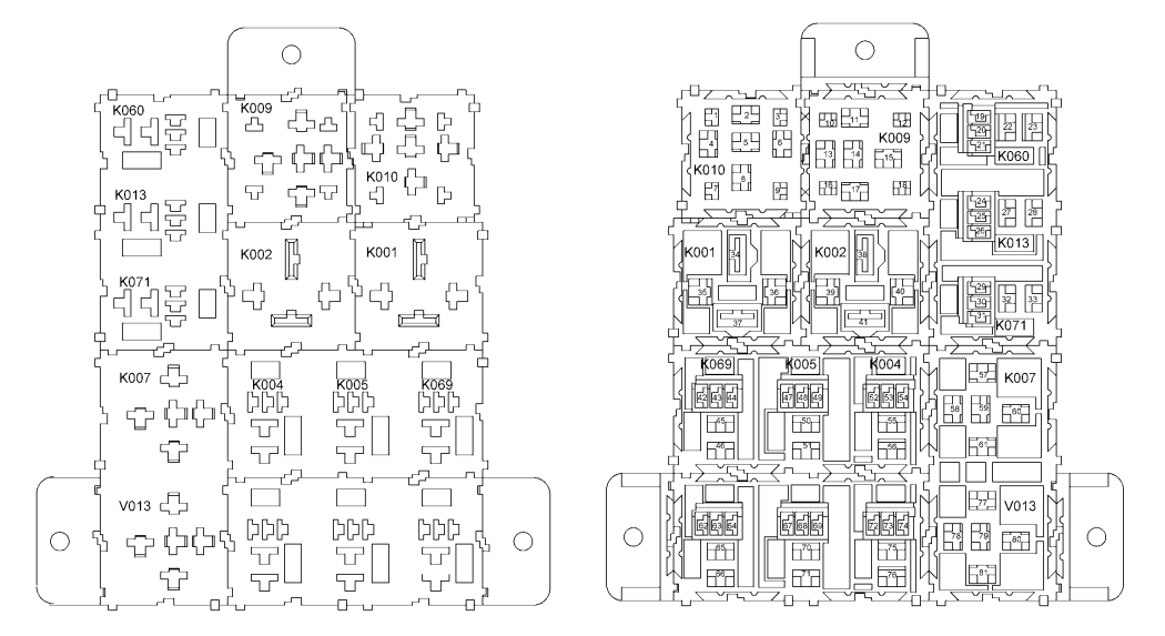
K002 Relais +UB 58
K004 Relais 56A
K005 Relais 56B
K007 Relais Bremse
K009 Impulsgeber Scheibenwischer
K010 Relais Blinkgeber
K013 Relais 3. Hydraulikkreis
K060 Relais TK-Ventil
K069 Sperr relais
K071 Relais 4 Hydraulikkreis
V013 Diodengruppe