
Claas DISCO, CORTO, VOLTO, LINER Fuse Box Diagram. Relay
DISCO 8500C (Tractor) DISCO 8500C-6, -8 (JAGUAR) Fuse box location.
Central terminal compartment JAGUAR 8550C
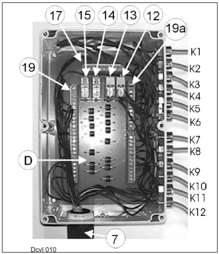
7 Central terminal compartment connector
12 Lock-up valve unit 89 and 99 relay
13 Relay for 4/3 way solenoid valve (item 50A)
14 Relay for 4/3 way solenoid valve (item 50B)
15 Relay for lock-up valve unit 109
17 Terminal strip, plus in central terminal compartment (located above the relays)
19 Left terminal strip
19 a Right terminal strip
K1 Raise/lower right side-mounted mower unit, solenoid valve 74
K2 Raise/lower left side-mounted mower unit, solenoid valve 73
K3 Front mower unit, solenoid valve 72
K4 Right mower unit lock-up valve unit, solenoid valve 89
K5 Left mower unit lock-up valve unit, solenoid valve 99
K6 Front mower unit lock-up valve unit, solenoid valve 109
K7 Fold out side-mounted mower unit, solenoid valve 70
K8 Fold in side-mounted mower unit, solenoid valve 71
K9 140 bar pressure switch, item 96
K10 140 bar pressure switch, item 96
K11 150 bar pressure switch (fold in side-mounted mower units), item 93
K12 150 bar pressure switch (fold out side-mounted mower units), item 95
D Diodes
Central terminal compartment, from 2000
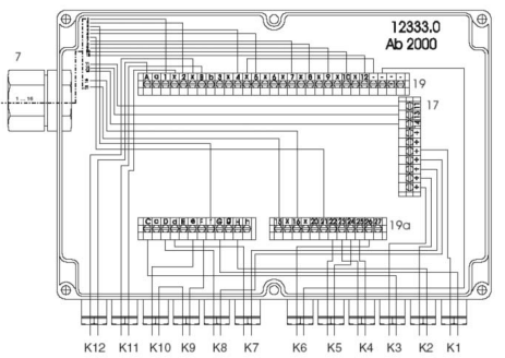
7 Central terminal compartment connector
12 Lock-up valve unit 89 and 99 relay
13 Relay for 4/3 way solenoid valve (item 50A)
14 Relay for 4/3 way solenoid valve (item 50B)
15 Relay for lock-up valve unit 109
17 Terminal strip, plus in central terminal compartment
(located above the relays)
19 Left terminal strip
19a Right terminal strip
K1 Raise/lower right side-mounted mower unit, solenoid valve 74
K2 Raise/lower left side-mounted mower unit, solenoid valve 73
K3 Front mower unit, solenoid valve 72
K4 Right mower unit lock-up valve unit, solenoid valve 89
K5 Left mower unit lock-up valve unit, solenoid valve 99
K6 Front mower unit lock-up valve unit, solenoid valve 109
K7 Fold out side-mounted mower unit, solenoid valve 70
K8 Fold in side-mounted mower unit, solenoid valve 71
K9 140 bar pressure switch, item 96
K10 140 bar pressure switch, item 96
K11 150 bar pressure switch (fold in side-mounted mower units), item 93
K12 150 bar pressure switch (fold out side-mounted mower units), item 95
Central terminal compartment, up to 2000
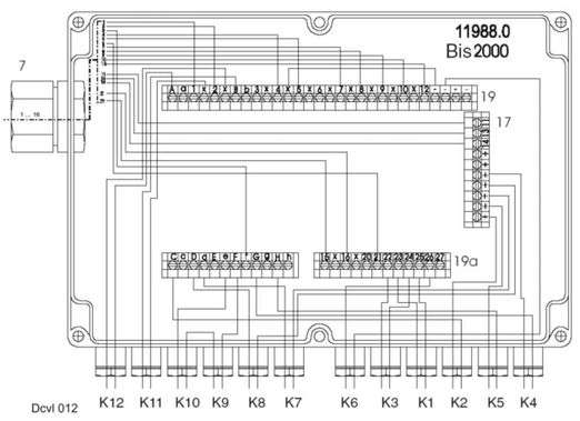
Differences as compared with central terminal compartment
ìfrom 2000î:
The assignment of inputs 1 to K5 is different.
The connecting terminals on the board have not been changed.
7 Central terminal compartment connector
12 Lock-up valve unit 89 and 99 relay
13 Relay for 4/3 way solenoid valve (item 50A)
14 Relay for 4/3 way solenoid valve (item 50B)
15 Relay for lock-up valve unit 109
17 Terminal strip, plus in central terminal compartment (located above the
relays)
19 Left terminal strip
19a Right terminal strip
K1 Raise/lower right side-mounted mower unit, solenoid valve 74
K2 Raise/lower left side-mounted mower unit, solenoid valve 73
K3 Front mower unit, solenoid valve 72
K4 Right mower unit lock-up valve unit, solenoid valve 89
K5 Left mower unit lock-up valve unit, solenoid valve 99
K6 Front mower unit lock-up valve unit, solenoid valve 109
K7 Fold out side-mounted mower unit, solenoid valve 70
K8 Fold in side-mounted mower unit, solenoid valve 71
K9 140 bar pressure switch, item 96
K10 140 bar pressure switch, item 96
K11 150 bar pressure switch (fold in side-mounted mower units), item 93
K12 150 bar pressure switch (fold out side-mounted mower units), item 95

When the 3/3 way raise front attachment solenoid valve is actuated on
the forage harvester, the Reed switch*75 connects earth to relay 15,
terminal 85 and relay 12, terminal 85.
Relay 15 cuts the current to the lock-up valve unit 109.
Relay also cuts the current to the lock-up valve units 89 and 99 (the lock-
up valve units are closed when deenergized).
When raising is complete, the mower unitsí weight generates a pressure
of > 85 bar in the cylinders of the Jaguar front attachment.
The oil pressure switch 94 connects earth to relay 12, terminal 85 as long
as the pressure in the lift cylinders is > 80 bar.
Relay 12 switches and cuts the power supply to the lock-up valve units
89, 99 and 109.
This is necessary to make the mower units remain in their position when
lifting is complete on the turning area. When the pressure in cylinders 90
and 100 rises to above 140 bar, the oil pressure switches 96 open briefly.
Earth connected to relay 12, terminal 85 drops out and the relay connects
the current supply to the lock-up valve units 89 and 99.
The lock-up valve units open and the accumulators receive oil from the
ram rod end (from the front attachment cylinders on the Jaguar) so that
there is no oil loss and no oil can flow from the system into the tank
(pressure relief valve 104).
* On the Jaguar 800, the Reed switch connects earth.
On the Jaguar 600, earth is supplied directly from the 3/3 way ÑRaiseì
solenoid valve.