
TH360B Telehandler Fuse box diagram & Relay
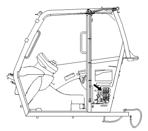
The fuse panel is located behind an access cover in
the left side of the cab arrangement. Remove the
cover in order to expose the fuses and relays.
Replace fuses with the same type and size only.
Otherwise, electrical damage can result.
If it is necessary to replace fuses frequently, an
electrical problem may exist. Contact your Caterpillar
dealer.
The fuses protect the electrical system from damage
that is caused by overloaded circuits. If the element
inside the fuse separates, replace the fuse. Check
the circuit if the element is separated in the new fuse.
Repair the circuit, if necessary.
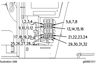
Illustration 268 shows the location of the fuses. The
fuses are numbered from the top to the bottom.
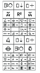
A film with the positions of the fuses is located on the
inside of the access cover. The location of the fuse
matches the location of the pictograph on the film.
Frame Level (1) - 10 AMP
Differential Lock (2) - 10 AMP
Front Window Wiper (3) - 10 AMP
Rear Window Wiper (4) -15 AMP
High Speed Air Conditioner Blower (5) -
25 AMP
Low Speed Air Conditioner Blower (6) -
15 AMP
Hydraulic Auxiliary Circuit (7) - 10 AMP
Steering Alignment (8) - 10 AMP
Joystick Control (9) - 10 AMP
Spare Position (10)
Access Platform (11) - 10 AMP
PHS Circuit (12) -15 AMP
Turn Signals (13) - 10 AMP
Work Light (14) -10 AMP
Horn (30) -10 AMP
Electrical Monitoring System (31) - 15 AMP
Electrical Monitoring System (32) - 20 AMP
Work Light (15) -10 AMP
Rear Work Lights (16) - 10 AMP
Engine Start (17) - 10 AMP
Hazard Flashers (18) - 10 AMP
Left Side Parking Light, Left Side Rear
Light, and License Plate Light (19) - 15
AMP
Right Side Parking Light, Right Side Rear
Light, and Fog Light (20) - 15 AMP
Rotating Beacon (21) - 10 AMP
Alternator Indicator Light and Oil
Pressure Indicator Light (22) - 15 AMP
Seat Height Adjustment (23) - 10 AMP
Radio which is Independent of Engine Start
Switch (24) -10 AMP
LH Tail Lights (25) -10 AMP
RH Tail Lights (26) - 10 AMP
Engine Run (27) -10 AMP
Fuel Pump (28) - This fuse is not used on
this machine.
Radio which is dependent of Engine Start
Switch (29) -10 AMP
Relays
Note: Your machine may not utilize all of the relays that
are listed here. You should only replace these relays
with relays of the same type.
Indicators and Gauges - Test
Check for broken indicator lights, broken switches or
broken lenses on the instrument panel gauges.
Start the engine. Run the engine until the instrument
panel gauges have stabilized. Check that the
instrument panel gauges are operating correctly.
Stop the engine and perform any necessary repairs
before the machine is operated.
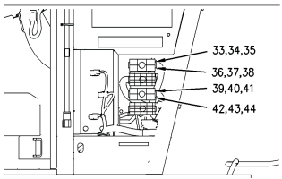
Fuel Pump (33)
Ground for Quick Coupler (34)
Power for Quick Coupler (35)
Crab Steering (36)
Reverse Backup Lights (37)
Circle Steer (38)
Frame Level (39)
Ground for Auxiliary Diverter Valve (40)
Power for Auxiliary Diverter Valve (41)
Differential Lock (42)
Fuel Pump (43)
Engine Solenoid (44)
Caterpillar Engine, Service Manual, Wiring Diagrams (Error Codes)>>
Caterpillar Engine Error Codes>>